Systematic methods for controlling feature suppression states, preventing dangling geometry references, and maintaining stable parametric models across multi-variant families.
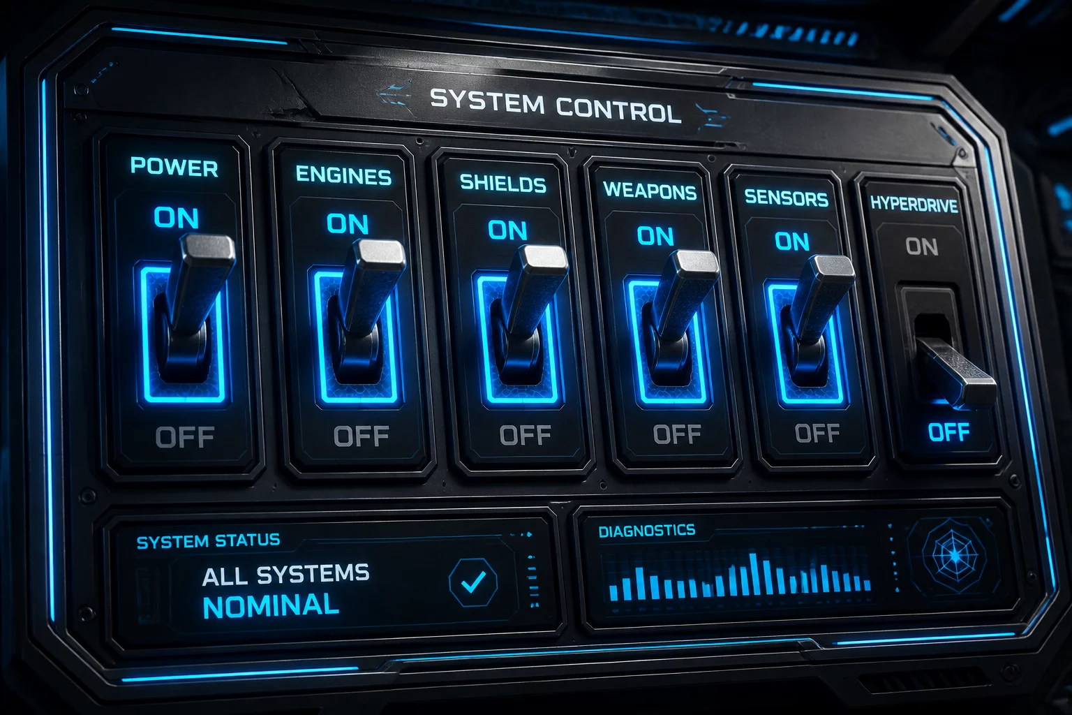
In configurable CAD models, feature toggles allow engineers to activate or suppress specific geometric operations based on top-level configuration inputs. Rather than building separate part files for variations like mounting tabs, port cutouts, or cooling fins, a single unified model handles these differences through structured toggle conditions.
Uncontrolled feature suppression often introduces downstream rebuild errors when dependent features lose their sketch planes or reference edges. Establishing a strict hierarchical toggle strategy isolates non-essential features, ensuring that core geometric bodies remain fully solved regardless of active variant selections.
A feature toggle must never act as a geometric parent to features required in baseline variants. When a fillet, hole pattern, or extrusion is toggled off, any sketch referencing its edges or surfaces fails immediately. To prevent these failures, anchor subsequent sketches to primary reference planes or stable parent geometry that remains unsuppressed across all family variants.
Never attach invariant sketches or downstream features to geometry generated by a toggled feature. Always reference permanent datum planes, primary coordinate origins, or root reference bodies.
Combining multiple related features into a dedicated folder or grouped tree node simplifies state tracking. When an entire optional subsystem—such as an integrated bracket or conduit port—is controlled by a single boolean toggle, managing group suppression keeps the configuration matrix clean and predictable.
Reference only persistent root geometry to guarantee zero dangling edges when optional features are toggled off.
Group inter-dependent optional features together so they suppress simultaneously without leaving orphaned operations.
Standardize boolean toggle naming in the configuration table to clearly communicate intended mechanical behavior across teams.
David Clark is a CAD systems specialist specializing in parametric variant architecture, modular feature logic, and enterprise product configurator design.
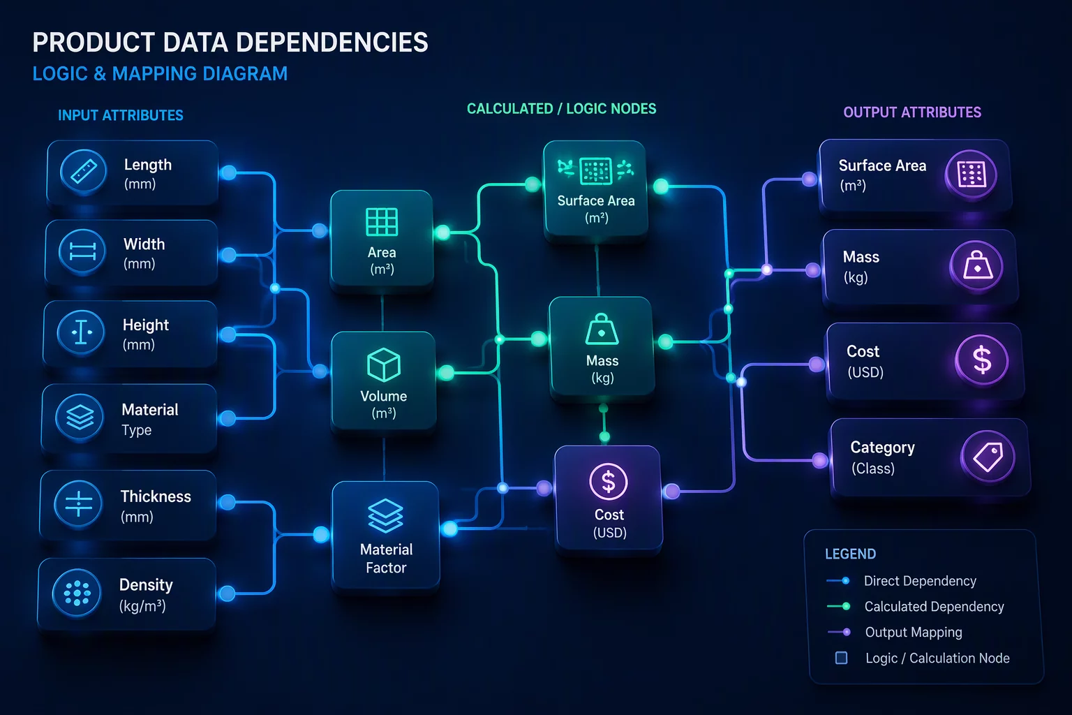
Learn how to map complex input dependencies and prevent contradictory parameter combinations in CAD models.

Establish discrete selection lists and bounds for input parameters to keep parametric variants strictly compliant.

Discover systematic strategies for filtering out geometrically impossible or commercially unviable variants.