
Logic 01
Defining the Boundary
Define the true boundary of a product family. Establishing clear perimeter constraints prevents configuration explosion and invalid downstream geometry.

Engineering frameworks for defining modular boundaries, isolating independent inputs, and preventing variant combinatorial explosion in parametric CAD models.
Explore foundational methods for scoping parametric boundaries, calculating derived inputs, and enforcing standardized variant matrices.
Logic 01
Define the true boundary of a product family. Establishing clear perimeter constraints prevents configuration explosion and invalid downstream geometry.
Logic 02
How to identify truly independent inputs. Isolating primary drivers from dependent formulas keeps variant tables clean and deterministic.
Logic 03
Methods for calculating derived parameters. Automating secondary dimensions through expressions reduces manual variant table entries.
Logic 04
Understanding physical versus commercial limits. Separating manufacturing envelope restrictions from commercial catalog offerings.
Logic 05
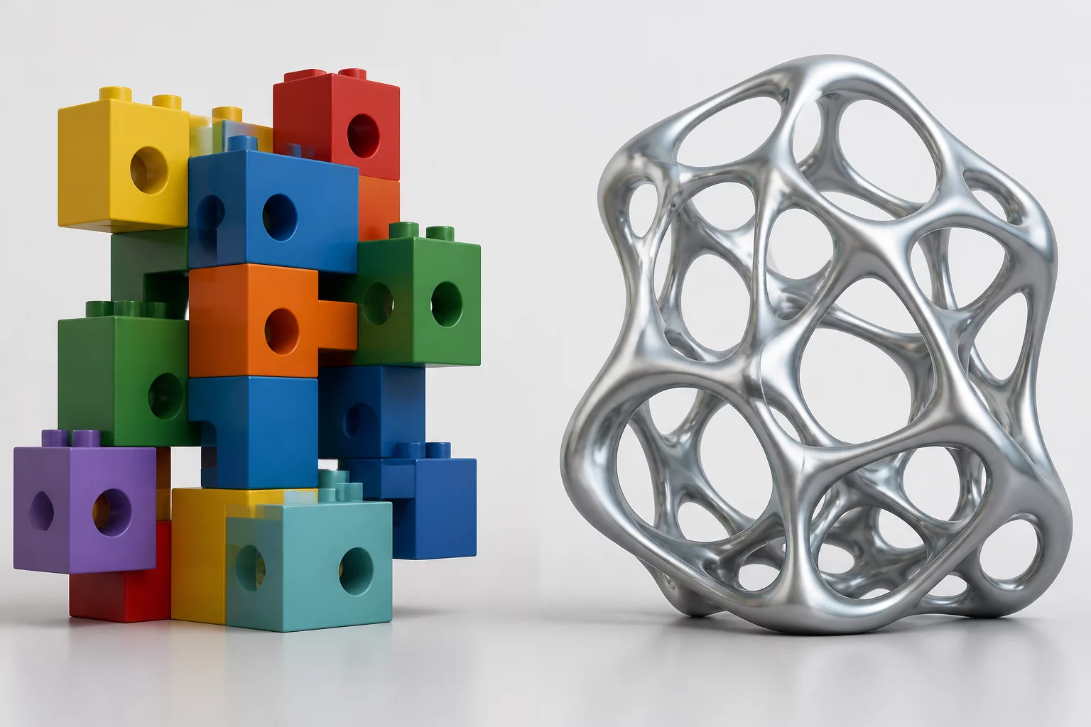
Comparing modular and parametric design approaches. Choosing between discrete swappable components and continuous dimensional scaling.
Logic 06
When to use option forks versus configurations. Determining when discrete branch logic requires distinct part studios versus table variations.
Logic 07
Best practices for standardizing variants. Ensuring released product families maintain strict compatibility across engineering releases.
A product family boundary is reached when changes in functional topology or manufacturing processes require distinct master sketches and assembly hierarchies rather than parametric table shifts.
Independent inputs represent direct customer or functional requirements, whereas derived parameters are calculated programmatically through expressions to guarantee mechanical integrity without cluttering input fields.