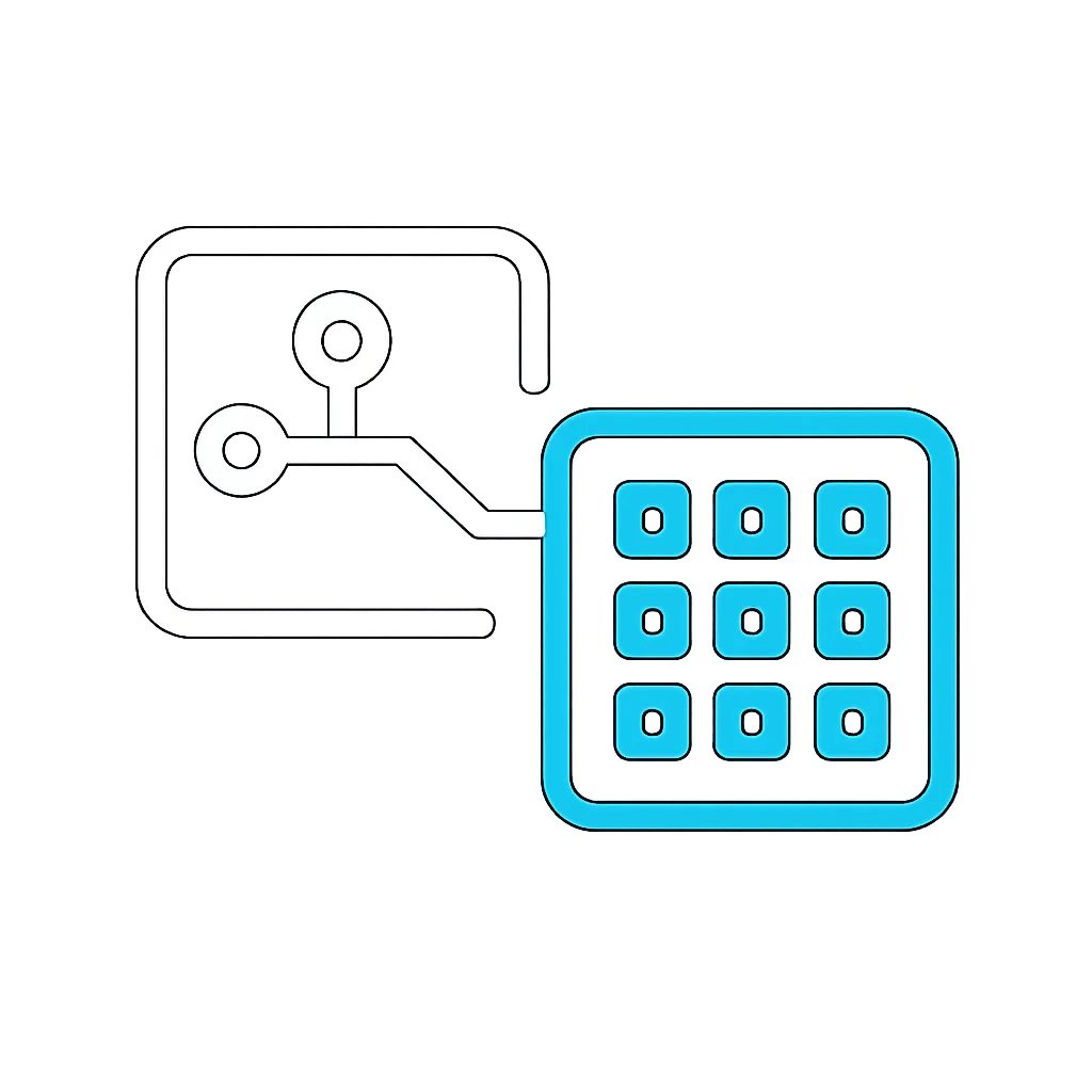
Understanding the structural trade-offs between discrete swappable component interfaces and continuous equation-driven geometric deformation in scalable product families.

Modular design establishes boundaries around discrete components that mate via standard physical and digital interfaces, while parametric design relies on continuous mathematical relationships to alter dimensions, clearances, and features dynamically. In mechanical modeling, modularity isolates downstream failures by keeping part files rigid and interchangeable, whereas parametric systems adapt a single master geometry across infinite intermediate sizing points.
Choosing between these approaches dictates file regeneration overhead, downstream drawing automation, and supply chain simplicity. Overly parametric systems often trigger topological rebuild failures when geometric parameters cross inflection points, whereas purely modular platforms can produce catalog sprawl if every minute size variation requires dedicated physical tooling.
High-performance CAD systems balance modularity at the assembly envelope with parametric flexibility inside individual subassemblies. Standard mount points, electrical conduits, and fastening grids remain strictly modular, while internal brackets and enclosure depths resize parametrically based on external user requirements.
Never allow parametric dimensional variations to deform common mounting interfaces. Shared assembly surfaces must remain invariant across all configuration states to preserve modular cross-compatibility.
Applying this principle ensures engineering teams configure custom customer variants in seconds without risking broken assembly constraints or misaligned mating hole patterns in production models.
Apply modular configurations when inventory standardization, supplier batching, or field-swappable hardware assemblies govern manufacturing economics.
Deploy parametric dimensions when custom spatial fit, load calculations, or enclosure sizing demand continuous scaling between defined minimum and maximum limits.
Isolate parametric complexity inside single Part Studios rather than allowing dimensional variables to propagate through multi-tiered assembly trees.
David Clark specializes in mechanical CAD infrastructure, variant table optimization, and top-down product architecture for configurable hardware systems.

Establish strict limits between configurable inputs and invariant geometry to protect CAD performance.

Methods for computing secondary structural variables automatically from primary user selections.

Identify when distinct product variations require separate documents versus unified configuration tables.