Establish strict geometric boundaries, tolerance intervals, and continuous parameter safeguards to keep parametric models manufacturable and numerically stable.
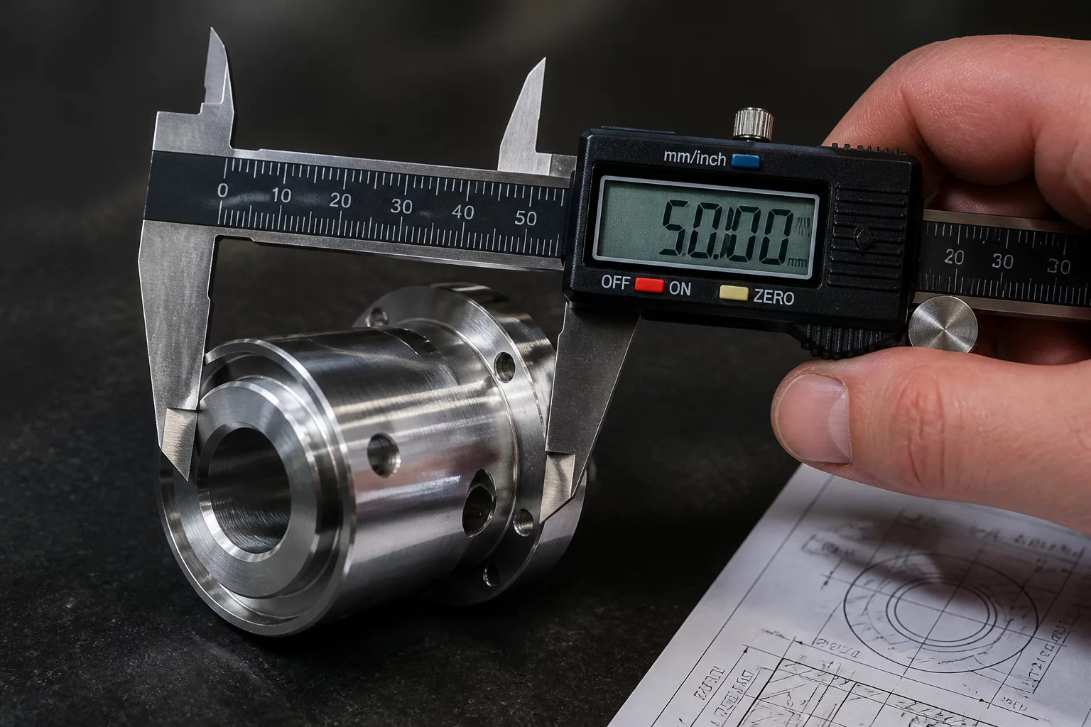
Parametric CAD systems regenerate solid models based on variable inputs, but unconstrained dimensions frequently cause topology collapse, self-intersecting geometry, and downstream drafting errors. When a designer or automated CPQ system inputs a continuous dimension without boundary guardrails, fillets can invert, wall thicknesses can drop below manufacturing minimums, and mating clearance holes can intersect adjoining ribs.
Configured models require strict lower and upper dimension limits anchored directly to physical fabrication tooling capabilities, structural safety margins, and component supplier catalogues. Restricting numeric values through declarative configuration rules transforms risky open-ended models into deterministic, production-ready parametric assemblies.
Dimension limit governance falls into two primary structural tiers: absolute hard-stops and contextual formula clamping. Absolute hard-stops establish immutable ceiling and floor values for primary lengths, widths, and diameters. Contextual clamping dynamically shifts those limits based on secondary configuration selections, such as stepping down the maximum allowable length when selecting a thinner sheet-gauge material.
Every dynamic dimension variable must evaluate through a bounding equation: dimensionValue = clamp(input, minBoundary, maxBoundary). This guarantees that out-of-range user inputs automatically truncate to the nearest safe extreme rather than triggering catastrophic CAD rebuild failures.
Stepped increments further refine dimension control by snapping continuous inputs to discrete standard manufacturing stock sizes. This eliminates arbitrary fractional variations that drive up tooling changeover expenses and lead times on the shop floor.
Define minimum wall thicknesses and bend radii as derived functions rather than independent numeric inputs.
Implement mathematical clamp functions at the top-level configuration variable table before downstream sketches consume the data.
Align maximum dimensional ceilings with standard transport crating, CNC travel limits, and sheet stock sizes.
Emily Davis is a lead mechanical systems architect specializing in complex configuration tables, parametric CAD governance, and automated variant modeling.

Establish strict allowed values for continuous and discrete configuration inputs.

Strategies for pruning invalid dimension combinations and impossible variant branches.

Managing automated feature suppression and conditional geometry based on size bounds.