Establishing rule-driven fastener patterns, load-bearing geometry matrices, and clearance tolerances across configurable bracket mounting assemblies.
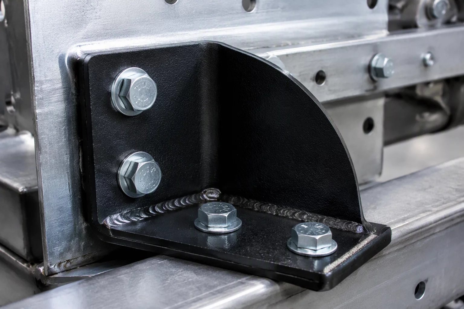
Configurable bracket assemblies present acute risk of physical interferences when dimension ranges expand independently of standard hardware spacing. In parametric CAD platforms, modifying an overall enclosure dimension often leaves secondary mounting flanges stranded or causes fastener holes to intersect with internal structural gussets. Establishing deterministic mounting rules ensures every variant generated maintains physical compatibility with standard hardware.
Instead of permitting arbitrary continuous dimensions, the bracket mounting logic utilizes discrete dimensional increments linked to standardized bolt center distances. This eliminates custom machining for non-standard pitch spacing and guarantees that standard M4 through M12 fastener sets interface correctly regardless of the selected bracket orientation.
Mounting bracket parameters depend directly on the primary structural beam thickness and total supported mass. When configuring the bracket variant, the logic table evaluates the required load rating and calculates the minimum sheet gauge and required bolt array configuration automatically.
For structural brackets carrying dynamic loads, hole edge distance must adhere to E >= 1.5 * d_hole, and minimum pitch distance P_min = 3 * d_hole. If total cantilever length exceeds 250 mm, the configuration logic enforces a mandatory stiffening rib feature toggle and restricts mounting plate thickness to a minimum of 4.0 mm.
The configuration matrix disables thin-gauge profiles whenever high-torque hardware options are selected, preventing sheet metal deformation during assembly torque-down. Assembly mates reference named geometry points rather than transient edge references, preventing broken mates when hole patterns scale up or down.
Tie hole pattern arrays to discrete pitch parameters instead of arbitrary float variables to maintain tooling standard compliance across all manufactured sizes.
Implement conditional feature toggles for stiffening ribs based on cantilever overhang limits to guarantee structural integrity without manual recalculation.
Use mate connector coordinate systems pinned to primary datum features to ensure downstream assembly references never detach during variant reconfiguration.
Senior Mechanical Systems Specialist at ConfigurationLogic Atlas focusing on parametric sheet metal architectures, kinematic variant rule matrices, and standardized assembly constraints.
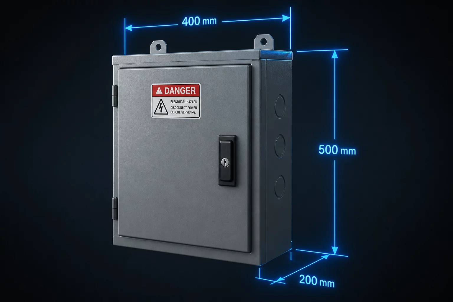
Rules for sizing industrial electrical enclosures with dynamic dimensional limits and thermal clearances.

Configuring harness routing channels, bend radius checks, and retention clip placements.

Ensuring surface coating treatments and protective finishes match environmental exposure requirements.