Establishing systematic parametric boundaries, internal clearance calculations, and dimensional stepped ranges for robust industrial housing configurations.
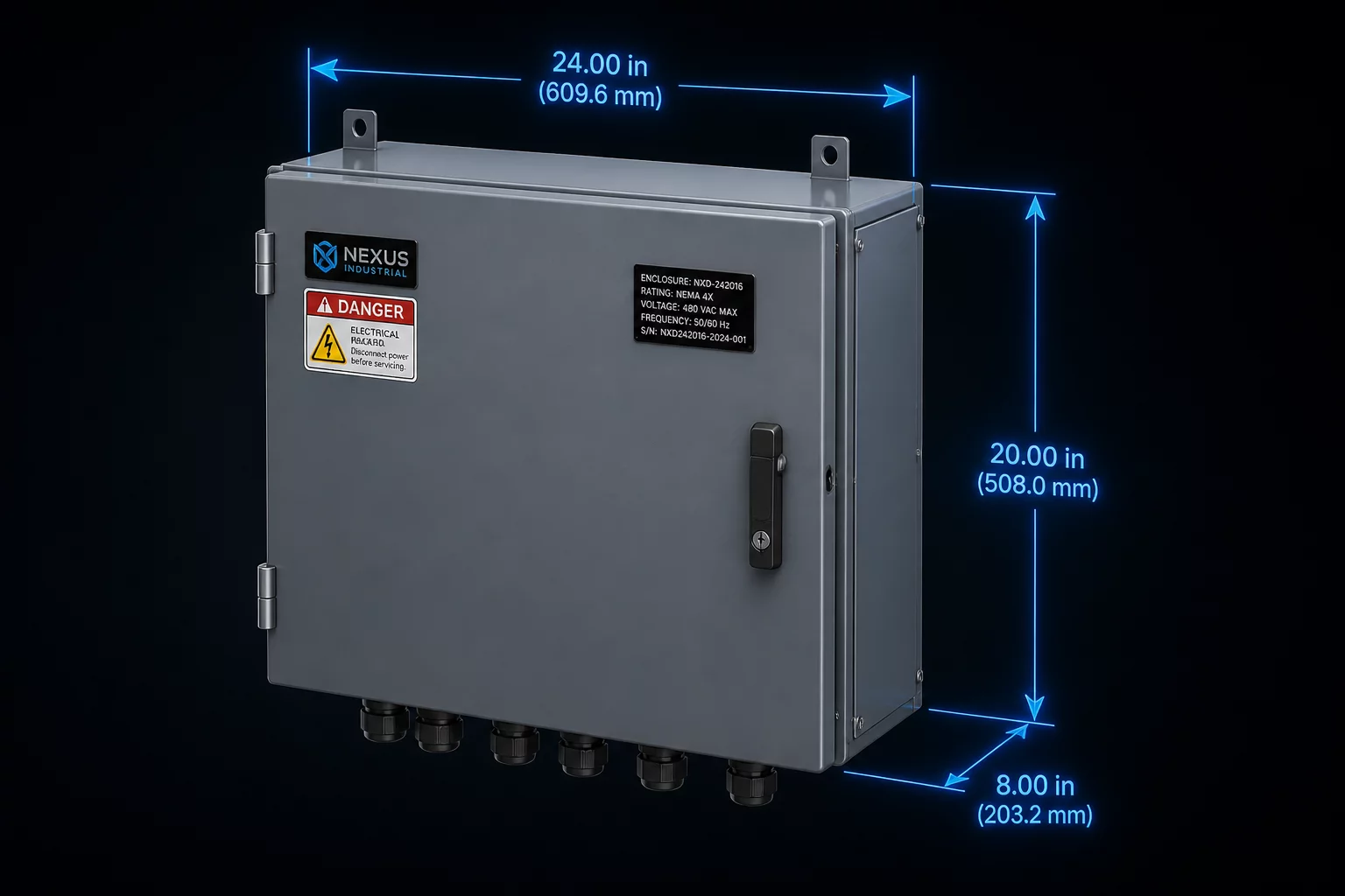
Industrial enclosure sizing frequently falls into the trap of continuous unconstrained parameter entry. When engineers enter arbitrary width, height, and depth dimensions into CAD configurators, internal layout components like DIN rails, terminal blocks, and cooling fans break alignment or violate electrical spacing standards.
Systematic enclosure sizing logic converts continuous user dimensions into discrete standard manufacturing steps while calculating mandatory keep-out zones and internal volume derating factors automatically.
Sizing logic initiates with component bounding boxes rather than external shell boundaries. The configuration engine aggregates component bounding dimensions, applies high-voltage clearance margins, adds thermal dissipation buffers, and resolves the smallest permissible standard chassis envelope.
Continuous inputs evaluate against standard modular sheet-metal punch increments (typically 25mm or 50mm steps). If internal thermal load exceeds 35W per cubic decimeter, forced convection duct zones are automatically inserted into the height and depth dimension arrays.
When auxiliary modules such as heavy transformer mounts or high-density gland plates are selected, mounting flange offsets update synchronously, preventing interference with internal sub-panel bolt patterns.
Drive external dimensions from interior payload envelopes, never vice versa.
Enforce discrete dimension snapping to match standard stamping and brake-forming tooling.
Lock thermal convection clearance zones as immutable geometric keep-outs across all variant states.
Senior Systems Architect specializing in rule-based CAD automation, variant configuration matrices, and scalable parametric assembly frameworks.
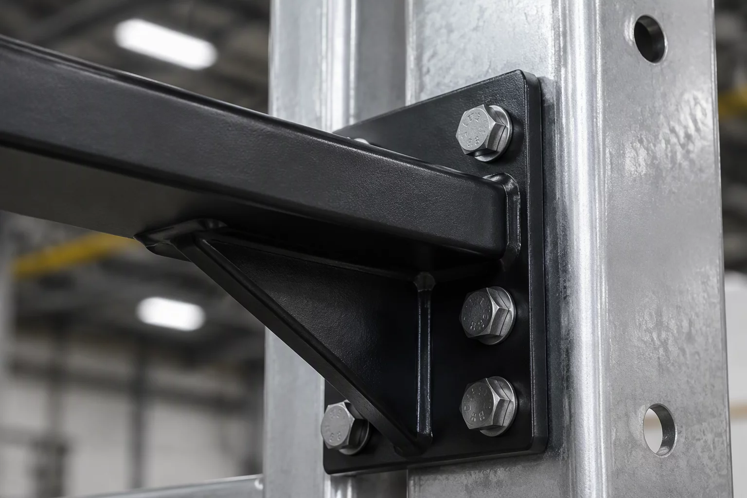
Systematic placement algorithms and fastener spacing rules for modular mounting bracket configurations.
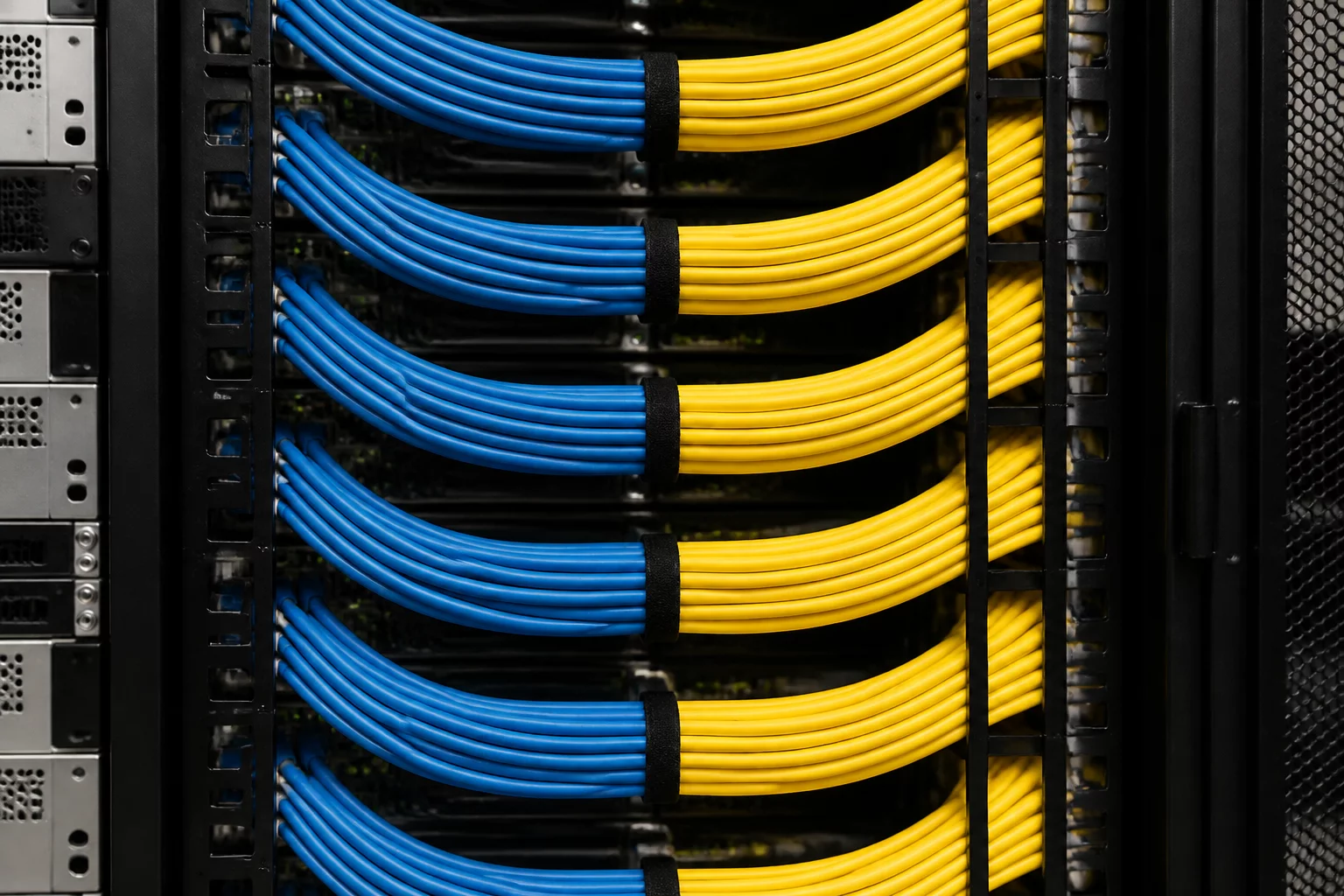
Parametric bundle clearance paths, bend radius validation, and trunk conduit allocation logic.
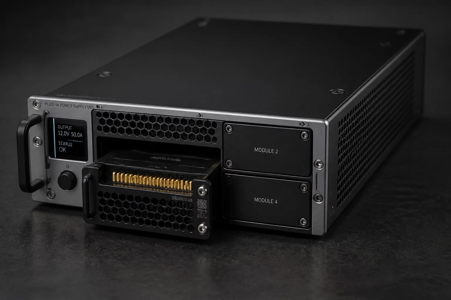
Validating wattage requirements, redundancy brackets, and electrical rail compatibility logic.