Defining structural constraints, thermal wattage headroom, and form-factor pairing to prevent impossible power supply configurations in parametric assemblies.
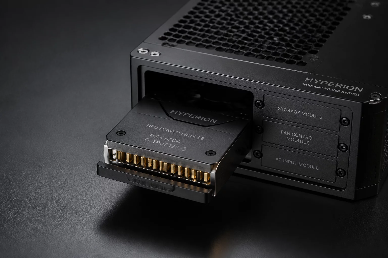
In modular industrial machinery, selecting the correct power supply module is not a standalone electrical decision. Physical geometry, DIN rail pitch, terminal block orientation, and convective airflow clearances directly dictate which chassis configurations can mechanically accept a specific wattage module. Without strict configuration rules, product configurators frequently allow 480W modules into compact enclosures designed strictly for 120W thermal dissipation envelopes.
Engineering teams must link electrical demand metrics with spatial bounding boxes inside the parametric model. When a user or system engineer chooses high-torque stepper drivers or auxiliary heated bed options, the configuration logic must automatically constrain the module selector to high-capacity units while simultaneously validating minimum standoff distances and cable exit clearances.
Power supply variants generally fall into standard form factors: open-frame, enclosed cage, DIN-rail mounted, and redundant hot-swap bays. Each tier introduces distinct bolt hole patterns and cooling boundary constraints. A robust variant table enforces one-way conditional logic where increasing load current recalculates chassis depth requirements.
If Total_Connected_Load_Watts * 1.25 exceeds Module_Rated_Capacity, the configurator forces the next wattage tier. If the selected module height exceeds Enclosure_Internal_Z_Clearance minus 40mm airflow buffer, Enclosure_Depth parameter automatically increments to the next standard bracket size.
By embedding this relational check inside the assembly definition, CAD models update cleanly without broken mate references. Fastener patterns on the mounting plate suppress or unsuppress automatically depending on the module vendor footprint assigned in the configuration matrix.
Tie wattage thresholds directly to enclosure volumetric thermal allowances to prevent selecting uncooled high-power units in sealed NEMA boxes.
Use conditional suppression arrays for mounting hole patterns so plate drill drawings update dynamically with power module swaps.
Enforce strict connector clearance zones at the CAD level to guarantee adequate bending radius for high-gauge DC output wiring.
Senior electro-mechanical engineer focusing on parametric logic, assembly configuration trees, and modular hardware constraints.
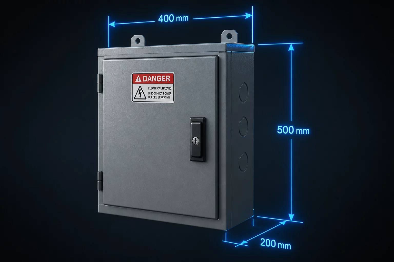
Determining parametric internal enclosure dimensions based on component volume and heat dispersion margins.
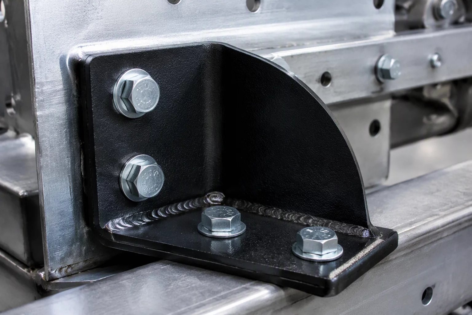
Structuring bracket placement logic to prevent fastener collisions and maintain mechanical integrity.
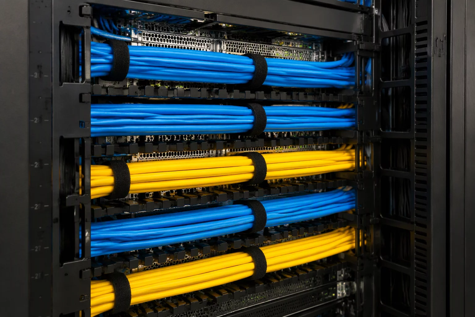
Rules for routing channel clearances, bend radii tolerances, and wire bundle segregation in assemblies.