Establishing deterministic port assignments, pathway volume checks, and bend radius constraints across parametric enclosure product families.
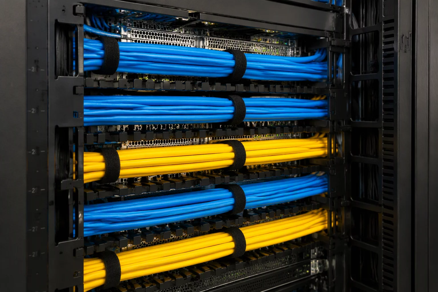
In modular industrial design, cable routing configurations determine how electrical harnesses, pneumatic lines, and fiber runs traverse an enclosure without geometric collision or assembly conflict. When product variants scale across multiple frame sizes, routing pathways cannot remain static sketches. They must adapt dynamically to internal component placement, wall cutouts, and thermal exclusion zones.
By defining parametric reference planes and dynamic centerline trajectories, engineers establish predictable conduit channels. This setup prevents harness pinch points, enforces minimum bend radii under high-density wiring scenarios, and guarantees that downstream assembly documentation updates automatically as users swap connector interfaces or cable gland layouts.
Cable routing logic relies on three interdependent tiers: input port selection, intermediate pathway clearance, and termination gland compatibility. If an enclosure depth shrinks below 300 mm, high-gauge industrial trunking cannot execute a 90-degree bend without violating the minimum bend radius of 65 mm. The configuration engine must immediately restrict high-gauge harness options or switch the gland plate to a side-entry variant.
For every configuration instance where enclosure depth is less than 350 mm, heavy trunk cable options (diameter > 28 mm) require top or bottom entry gland plates with offset brackets. Side-entry straight runs are suppressed automatically to maintain minimum bend radius safety margins.
Furthermore, internal cable tie anchors and partition walls toggle their suppression state according to selected routing paths. When multi-channel isolation is activated (separating 400V power lines from 24V sensor circuits), the model inserts an internal shielding duct and updates the bill of materials with corresponding DIN rail brackets and fire-retardant grommets.
Establish sweep paths based on offset sketch vertices rather than fixed model edges to maintain associativity across dimension changes.
Couple gland plate knockout patterns directly to selected cable diameter ranges through a table-driven suppression matrix.
Implement automated volume interference checks between maximum harness sweep envelopes and movable internal chassis components.
Michael Brown specializes in electromechanical configuration rules, CAD variant modeling, and parametric harness automation for industrial automation enclosures.
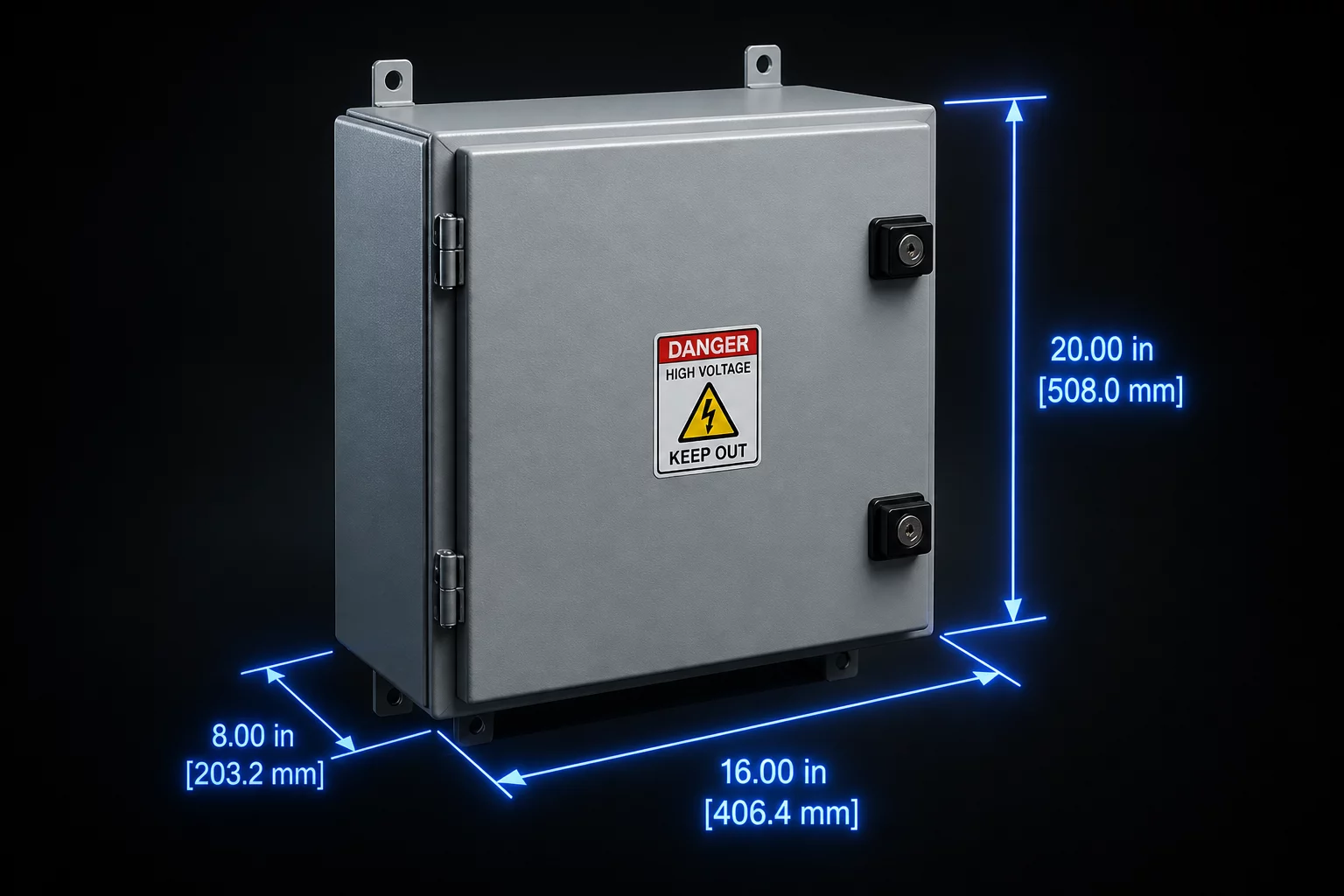
Managing dynamic dimensional dependencies, wall thickness scaling, and internal volume calculations across modular industrial cabinets.
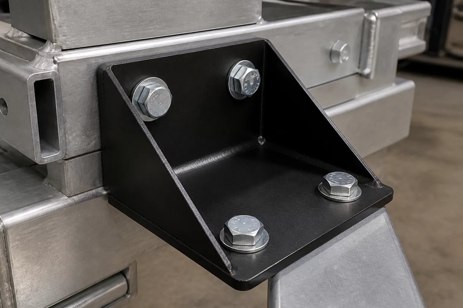
Establishing load-bearing fastener spacing, slot alignment constraints, and multi-position mounting hole matrices.
Configuring wattage capacities, thermal dissipation clearances, and busbar attachment options in modular power racks.